


Troubleshooting
Status:
Two lights indicate the device operational status:
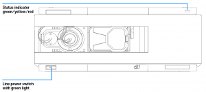
| Lights | Module condition | Explanation |
| Status light OFF and power supply light ON | Prerun mode | Module ready to begin an analysis. |
| Green status light | Run mode | Module performing an analysis. |
| Yellow status light | No-ready mode | Module waiting for a specific condition to be reached or completed. |
| Red status light | Error mode | An error has occurred during analysis. See the status display of the user interface to find the cause. |
| Blinking status light | Resident mode | Module is being updated |
| Fast blinking status light | Low-level error mode | Module must be rebooted / cold-started. A firmware update may be needed. If problem persists, replace Main Board or contact Moyo Scientific Service. |
Error messages:
Whenever an error occurs in the system, it will propagate through the CAN bus or APG remote cable. Depending on whether it occurred during a method run or not, the other modules will be informed and stopped, or will remain idle waiting for the system to be ready again.
General errors
The following is a list of errors regarding all HPLC modules:
| Message | Probable cause | Suggested actions |
| 0062 – Timeout |
|
|
| 0063 – Shutdown |
|
|
| 0070 – Remote Timeout |
|
|
| 0071 – Lost CAN Partner |
|
|
| 0064 – Leak |
|
|
| 0083 – Leak sensor open |
|
Contact Moyo Scientific Service. |
| 0082 – Leak sensor short |
|
Contact Moyo Scientific Service. |
| 0081 – Compensation sensor open | Defective Main Board | Contact Moyo Scientific Service. |
| 0080 – Compensation sensor short | Defective Main Board | Contact Moyo Scientific Service. |
| 0068 – Fan failed |
|
Contact Moyo Scientific Service. |
| 0205 – Open cover |
|
|
| Cover violation |
|
|
Detector related errors
The following is a list of detector specific errors:
| Message | Probable cause | Suggested actions |
| Visible lamp current |
|
|
| Visible lamp voltage |
|
|
| Calibration values invalid |
|
|
| Wavelength recalibration lost |
|
|
| Diode current leakage |
|
|
| Holmium oxide test failed |
|
|
| UV lamp current |
|
|
| UV lamp voltage |
|
|
| UV Ignition failed |
|
|
| UV heater current |
|
|
| Illegal value from temperature sensor mounted on the fan assembly |
|
|
| Illegal value from air inlet temperature sensor |
|
|
| Heater failed |
|
|
| Heater power at limit 0 means upper power limit hit (excessive ambient temperature drop). 1 means lower power limit hit (excessive ambient temperature increase). |
Ambient conditions have changed too much during the run, so that optimum results may not be guaranteed. |
|